Internal Building Communications
This includes the Doorbell, Intercoms and Panic Alarm. (generaly anything powered by the transformer in the techbox)
Contents
Intercoms
The handsets themselves are all hardwired together so that when any handsets are picked up at the same time users at each end may communicate. This means that without anyone calling anywhere else, a 4 way conversation is possible. When the phone is called, a loud buzz is produces by the speaker in the headset. If someone has the phone off the hook, you can’t call them (this is a good thing because then you can’t deafen the person holding the handset). Don't try and be funny by phoning yourself, those buttons are disabled so nothing will happen!
The phones are situated in 4 strategic locations around the building:
| Number | Location |
| 1 | Servery |
| 2 | Techbox |
| 3 | Dressing room |
| 4 | Box Office |
| 5 | Spare/Unused |
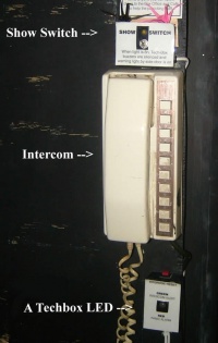
Back stage the intercom can be silenced by a small switch on the side of the unit. Regardless of whether it has been silenced or not, a small LED on the wall above the table will flash but nobody will ever see it.
In the Techbox, the phones can be silenced using the show switch. When the show switch is activated, the LEDs along the front of the Techbox will flash GREEN instead of hearing a beep.
Panic Alarm
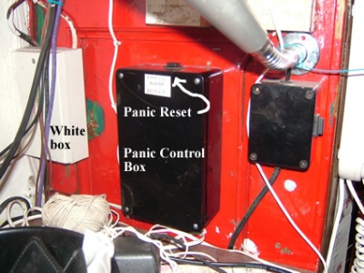
There are two panic buttons, one in the box office and one in the café, all members of staff should know how to use them. When they are pressed a blue light flashes in the office, red LEDs flash in the techbox. Additionally if box office is panics, a buzzer sounds in the café and the till will no longer open. The alarm is reset by pressing the button on the black box in the box office as shown in the pic. If you panic, you should have several hefty people there in seconds, people are discouraged from playing with it. If you are in another part of the building and the alarm is set of, please send any available personnel the help the panicking FOH staff
Once again: TO RESET THE ALARM press the ‘reset’ button on top of the black box in the box office (shown on right)
How it works
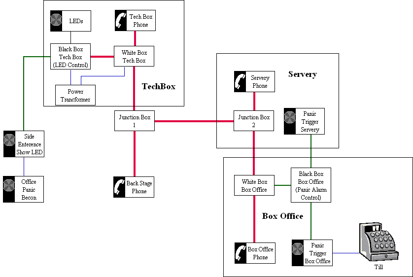
The alarm is controlled from the black box, the signal and power is transferred through the same wires as the intercoms. The interface of the two systems is in the white box to the left of the black control box
This system has its history in Bedlam folklore but it was modified to include the "silent" running mode with the red and green flashing LEDs around Spring 2000 by the skill and design work of the legendary Steve "Box Office" Fryatt.
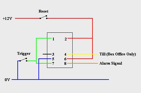
The alarm system is controlled from the black box in the box office. The panic alarm electronics are based around two relay switches this allows the system do be selective. If the box office alarm is triggered, an alarm is sounded in the café whilst cutting power to the box office till. These functions would not be desirable if the café alarm was triggered. The circuit diagram shown above represents one relay.
The pins 1 & 2 are used as the input to the relay. When there is no voltage difference between them, the pins 5 & 6 are connected to 3 & 4 respectfully. When there is a voltage over pins 1 & 2, pins 5 & 6 are connected to 7 & 8 respectfully.
Pin 5 is connected to 0V whilst pins 2 & 6 are connected to +12V this means that to cause the relay to close, pin 1 needs to be connected to 0V. This can be done by the trigger switch connecting pin 1 to 0V or by a feedback loop created when the switch is closed and pin 5 (0V) is connected to pin 7 which is hard wired to pin 1. To break the feedback loop, the reset switch is opened and the +12V power supply is interrupted.
Pin 8 is the alarm signal. When the alarm is activated, this line is set to +12V and triggers alarms in other parts of the building
Pin 3 is unused in both relays whilst pin 4 is only used in the box office relay. When the alarm is not activated, it is connected to 12V. This is used to supply power to the till. When the alarm is activated the power is no longer provided and so the till is effectively locked.
Box Office Till
While not related to building communications it is (as originally setup in 2006, reinstated in Autumn 2008 after the old till was broken) part of the panic alarm system and the opening system runs off the 12V transformer in the Techbox. The till currently in use is the old cafe till and is the opening system is a simple connection to the 12V supply (see image above) broken by a push button just above the till. When the panic alarm is set off the 12V supply is cut off and the button to open the till will cease to work until the reset button is pushed (the circuitry for this is in the black box with the panic reset switch - see diagram above). If the button stops working check the transformer is on you can also try turning the white push button - if all else fails the keys should be kicking around somewhere in the box office (possibly pinned to the wall).
Doorbell
The doorbell on the side entrance is attached to an old fire alarm which makes it loud enough to be heard anywhere in the building. It can be changed to a quiet buzzer mode which is for dress runs however this is often ignored/not herd to change it to the quiet mode swap the red switch on the side of the cupboard on your right as you enter the side entrance (behind the door). The small silver switch at the bottom f the box allows the doorbell to remain active the whole time. It can be turned off for shows at a switch in the techbox.
Power and Cables
The systems are all powered by a 12V transformer (though I think it is currently running at 13.8V) sitting under the tech box desk far end, stage right (under lighting desk). The panic alarm and phones are almost two separate systems that meet in the tech box and use the same cabling to speak to the tech box and other parts of the building. The cabling system is based on bell wire (12 cores).
Cable map
Please note that the cables are of the age that make them brittle buggers and liable to snap at any movement. This also means that they have faded and as such identifying the colours is a pain.
When two colours are listed, i.e. White/Blue this denotes White wire with Blue stripes.
| Channel | Name | Bell (12 core) | Phone |
| 1-Serv | Servery | Green/White | Black |
| 2-TB | Tech Box | White/Green* | D Brown |
| 3-BS | Back Stage | Brown/White | L Brown |
| 4-BO | Box Office | White/Brown | Purple |
| 5-SP | Spare | Grey/White | Orange |
| 6 | - | - | Yellow |
| 7 | - | - | Peach |
| 8 | - | - | White/Blue |
| 9 | - | - | Grey |
| 10 | - | - | Grey? |
| Incoming Call | - | - | White |
| Voice | Phone Line | Orange/White | Mint Green |
| + | +12V | Red/Blue | Red |
| - | 0V | Blue/Purple | Blue |
| PANIC | Panic Alarm Trigger | White/Orange | - |
*The White/Green wire between Box Office and Cafe has a break in it somewhere; this has been fixed by using the White/Grey wire over this section.
Junction box 1 is situated under the techbox just on the left as you enter the hole from stage right side (under light desk)
Junction box 2 is under the phone in the Servery


